Features
Multiple Blanking functions to improve work efficiency while ensuring safety
Through safe design and specifications compliant with international standards, we have exhaustively pursued higher levels of safety and realized higher work efficiency. This direct-projection safety device for press machines can be flexibly adapted to various work content and enables dramatically improved work efficiency
Fixed blanking functions and Floating blanking function to improve work efficiency while ensuring safety
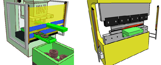
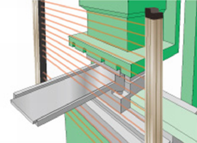
When a stationery object (e.g., device or material) is blocking certain beams during normal operation, these beams can be deactivated to enable operation of the press.
Function
Floating blanking
In normal sensor operation, a signal to stop the press is output if one beam is blocked, but using this function, a stop signal is only sent when two or more beams are blocked. This is useful when it is necessary to move objects in the sensor monitoring area
Fixed blanking
When a stationery object (e.g., device or material) is blocking certain beams during normal operation, these beams can be deactivated to enable operation of the press.
* A special controller is required to use the blanking functions.
Combination of Fixed Blanking and Floating Blanking
In addition to the fixed blanking function, there is a built-in dual optical axes blanking (floating) function. When multiple areas of beams are interrupted by obstacles(part of facility, materials and workpieces),combined use of two types of blanking function deactivate the interrupted beams and realize the efficient press operation without losing safety.
3 modes of Blanking Function
1. Fixed Blanking Mode
Multiple optical-axes interrupted area can be set as blanking area (up to 5 areas)
![]()
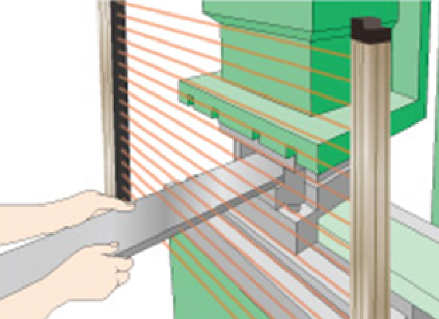
2. Fixed blanking mode with permissible optical axis
It is possible to move the monitoring area up to ± 1 optical axis above or below the fixed blanking setting area.
*When using allowable optical axis function
- To prevent influence of passing through of the materials and workpiece
- To prevent influence of shaking of the feeder or the conveyor by vibration of the press machine
Even in the above case, It is possible to continue work without interference when blocking certain beams within the permissible optical axes range.
![]()
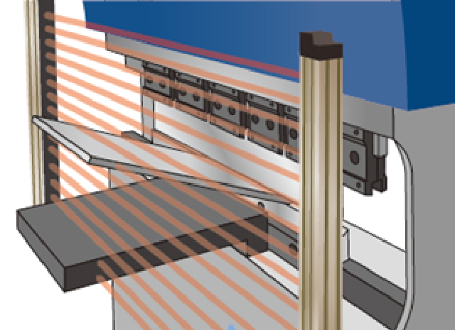
3.Combination of Fixed Blanking and Floating Blanking
When part of the equipment or workpiece is present in the sensor monitoring area, safe work is possible by blanking setting the corresponding area optical axes. It can correspond not only to fixed parts but also to movable parts.
![]()
Here is the point !
Visualize monitoring area and blanking area with LED display of dedicated control box
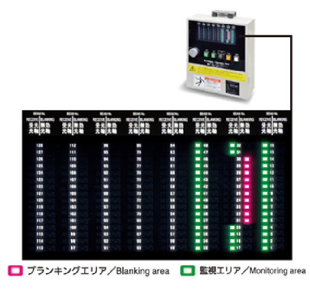
The front panel of the Blanking dedicated control box shows the state of the sensor’s total optical axes.
The LED display can grasp which part of the area is set blanking at a glance.
Blanking area easy to setup
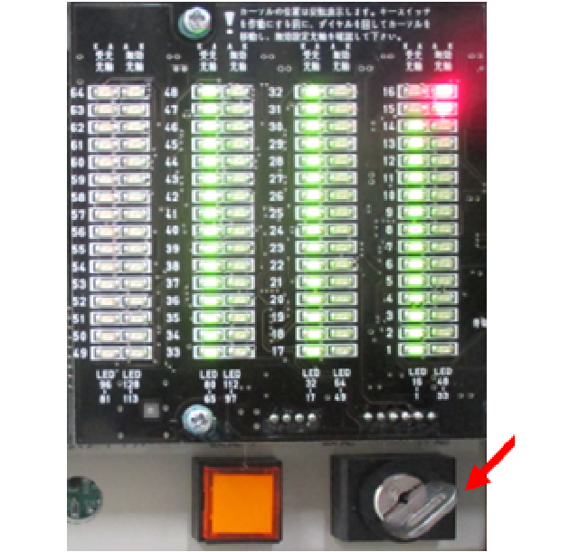
Easy blanking is possible by using only the key switch in the dedicated control box.
*Regarding the blanking setting key, please manage by the administrator such as press
work chief administrator.
Three types of blanking function enable safe and efficient work
- Fixed blanking function
- Fixed blanking function using allowable optical axis
- Blanking function combined protection with floating function
*Setting of mode can be easily changed by using the control box.
Applicable as an effective safety measure for press brake
Not affected by the interference in production, such as the followings.
- Material supply device
- Removal device such as robot
- Ejecting device such as conveyor
- Shooters for ejected materials and scrap
Others
Features
- The highest level safety has been realized based on a failsafe design that utilizes mutual checking performed by two CPUs equipped in the receiver, and redundancy of the signal-processing circuit and output circuit.
* Complies with international standard IEC61496-1/2 and North American standard UL61496-1/2. - The sensor is equipped with a Bypass function and Floating function
- *(Optional control box is required to use some functions)
- Diverse line-up to cope with various operating environments
- Select the optimal safety light curtain according to the installation environment, type of press and work content.
- Error indicator – Check details of errors with a single glance
- The number of lit LEDs indicates the reception status, enabling simple alignment of beams.
- Mounting brackets that significantly reduce influence of vibration
- Mutual interference prevention
Safety Device Selection Criteria (Protective Range)
- Mechanical press:(Die height + Stroke length) or more
- Hydraulic press:(Full daylight range) or more
*Note that the necessary protective range varies according to the installation conditions. - In the case that the top beam height at the time of installation is 1,400mm or less from the floor surface→(Die height + Stroke length + Insufficient length) or more
- In the case that the top beam height at the time of installation is more than 1,700mm from the floor surface
→(Die height + Stroke length – Excess length) or more *Lowest beam position is assumed to be the top surface of the bolster.
Specifications
- Standard specificationsRPX414 Series/RPX425Series
- Floating specificationsRPX414Series
- Floating specificationsRPX425Series
Standard specificationsRPX414 Series/RPX425Series
| RPX414-□□□X4 RPX414-□□□X2 |
RPX425-□□□X4 RPX425-□□□X2 |
|
|---|---|---|
| No. of beams | 26~234 | 13~125 |
| Protective height | 225~2097mm | 240~2480mm |
| Beam spacing | 9mm | 20mm |
| Minimum object sensitivity (MOS) |
14mm | 25mm |
Floating specificationsRPX414Series
| RPX414-□□□X4FL1 RPX414-□□□X2FL1 |
RPX414-□□□X4FL2 RPX414-□□□X2FL2 |
RPX414-□□□X4FL3 RPX414-□□□X2FL3 |
|
|---|---|---|---|
| No. of beams | 26~234 | 26~234 | 26~234 |
| Protective height | 207~2079mm | 189~2061mm | 171~2043mm |
| Beam spacing | 9mm | 9mm | 9mm |
| Minimum object sensitivity (MOS) |
23mm | 32mm | 41mm |
Floating specificationsRPX425Series
| RPX425-□□□X4FL1 RPX425-□□□X2FL1 |
|
|---|---|
| No. of beams | 13 ~ 125 |
| Protective height | 150~1755mm |
| Beam spacing | 20mm |
| Minimum object sensitivity (MOS) |
45mm |
Common Specifications
|
Detection distance |
X4-type:0.2~9m(Protection Height : 1620mm max.), 0.2~7m(Protection Height :1640mm min.) X2-type:0.2~4m |
|||||
|---|---|---|---|---|---|---|
| Response time | ON→OFF:10ms~27.5ms, OFF→ON:40ms~110ms *When Control Box is connected:ON→OFF:20ms~37.5ms, OFF→ON:60ms~130ms |
|||||
| Input voltage | 90VAC~240VAC(When Control Box is used)(Power Supply for Emitter/Receiver only:24VDC±20%) | |||||
| Power consumption | Emitter:76mA~165mA, Receiver:68mA~142mA (Control Box : CB6-S:16.8W, CB6-W: 30W) |
|||||
| Output contact(CB6) | 2A, 1B Contact Capacity : 250VAC 3A | |||||
| Key switch output contact(CB6) | 1A, 2B Contact capacity:220VAC 0.7A(Inductive Load), 1.0A(Resistance Load) | |||||
| Light source | Infrared LED(Wavelength : 870nm) | |||||
| Effective aperture angle | X4-type:Within±2.5° X2-type:Within±5°(when detection distance 3m or more) |
|||||
| External diagnostic function | When Test-input line or LA-terminal (in case with Control Box) is 9~24V:Emitter OFF(sink current : 3mA or less), When Test-input line or LA-terminal (in case with Control Box) is 0~1.5V or open : Emitter ON | |||||
| Ambient temperature | During operation:-10~55℃(No freezing), During storage : -30~70℃ | |||||
| Ambient humidity | During operation:35~85RH(No freezing), During storage : 35~95RH | |||||
| Ambient light intensity | Incandescent light : 3,000lx or less(light intensity at receiver surface), Sunlight : 10,000lx or less(light intensity at receiver surface) | |||||
| Insulation resistance | 20Mohm or more(for 500VDC) | |||||
| Withstand voltage | 1,000VAC(Sensor), 1,500VAC(Control Box), 50/60Hz, 1min. | |||||
| Degree of protection | Emitter/Receiver : IP65, Control Box:IP54(IEC60529) | |||||
| Vibration resistance | Malfunction Durability:10~55Hz, Double-amplitude:0.7mm, X,Y,Z directions : 20 sweeps | |||||
| Shock resistance |
Malfunction Durability:100/S 2 [10G], X,Y,Z directions 1,000 times |
|||||
| Standard compliance(sensor only) | X2-type:IEC61496-1-type ESPE & IEC61496-2-type2 AOPD IEC61508-1~-7(SIL1)、ISO13849-1:2006 Cat.2 PLc X4-type:IEC61496-1-type ESPE & IEC61496-2-type AOPD IEC61508-1~-7(SIL3)、ISO13849-1:2006 Cat.4 Ple |
|||||